

Understanding Primary Secondary Pumping Part 1: Behold the Humble Tee!
/By Chris Edmondson
Are you involved in the design or installation of hydronic systems? Do you anticipate becoming involved?
If you answered yes to either of these questions, this blog series on primary/secondary pumping will interest you. If you are a hydronic’s veteran, feel free to skip the first few blogs in the series – they may be too much of a review. Better yet, pass them onto a junior associate and sit tight for the more complex topics to come.
For now, we’re starting with the fundamentals, which are essential for anyone deeply involved in pumping system design or operation. As the series progresses, we want to get you

from here:
to here:
To do that, we’re going to start with the humble piping tee and a concept known as the “Tee Law.”
The Tee Law simply states that what goes in the opening(s) of the tee must come out the remaining opening(s). In other words, if you’ve got 150 GPM going into the tee, you’re going to have 150 GPM exiting the tee. That may mean that all of the flow is going straight through or flow is being split between the other orifices in some combination that equal to 150 GPM. (Figure 1)
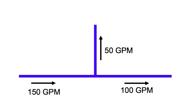
Figure 1
Sound simple? It is! That said, it’s very easy to lose sight of the simplicity of this basic law as systems become more and more complex. And yet, even the most complex systems (like the Primary Secondary Tertiary example below) are rooted in this one simple concept. So don’t lose sight of it.

Obviously, piping tees exist throughout any hydronic system, but let’s talk about the specific role they play in primary/secondary pumping. Figure 2 shows a simplified schematic of a primary/secondary piping system. At the bottom we see the primary piping (sometimes referred to as the “production piping”) and we see the secondary loop and cooling circuit that is connected to the primary piping at either end by two tees. These two tees (shown in green) represent what is often referred to as the common pipe.
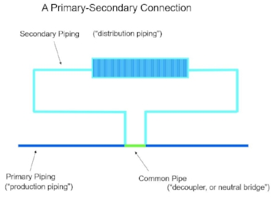
Figure 2
Let’s assume the primary pump is pumping 100 GPM. There is no valve installed in the common pipe and thus no interruption or pressure drop in the flow between the first and second tee of the primary loop.
So what’s happening in that secondary piping?
Not a thing. The flow from the primary pump (100 GPM) is going straight through both tees and the water in the secondary loop is just sitting there. All the action is in the primary loop. This is the basis for another common hydronic rule:
When two piping circuits are interconnected, flow in one will NOT cause the flow
in the other if there is no pressure drop in the piping common.
Now, consider what happens when we had a balancing valve in the common pipe and partially open it to allow just 35 GPM to pass through the common pipe. Now, instead of 100 GPM passing straight through the tee, we have 35 GPM passing through the tee. The remaining 65 GPM is diverted through the other opening of the tee and creating 65 GPM of flow through the secondary circuit. Remember – what goes in the tee must come out, and in this case 65 GPM is being routed to the secondary circuit and 35 is passing straight through the common pipe. (Figure 3)

Figure 3
Of course, primary/secondary systems typically consist of primary pumps and secondary pumps. So what happens if we add pump to the secondary loop? A secondary pump will establish flow in the secondary loop whether a balancing valve is present in the common pipe or not. In this case, we’ve installed a secondary pump that is generating 150 GPM of flow in the secondary circuit. Meanwhile, we still have just 100 GPM in the primary loop. Going back to the Tee Law, we know that you can’t have 100 GPM going in the Tee and 150 GPM coming out. So where is the other 50 GPM coming from?

Figure 4
The answer is in the common pipe. In this situation, we have created a reverse flow condition in the common pipe, with 100 GPM coming from the primary loop and 50 GPM from the secondary loop flowing to the left in the common pipe. (Figure 4) Intuitively you may know this is not an ideal scenario in many situations and we’ll get into why that’s the case later in this series. For now, it is important for you to understand that the Tee Law holds true, even if it means creating a reverse flow situation.
Again, without a pressure drop (balancing valve) in the common pipe, the flow through the primary and secondary loops will remain independent of each other. Only the flow that occurs in the common pipe will be impacted, and that is completely predictable, assuming you know what the flow in the both circuits is. One of the following three scenarios will always occur:
Flow Condition
Flow Direction in Common Pipe
(1) Primary Flow > Secondary Flow
Flow to the right
(2) Primary Flow < Secondary Flow
Flow to the left (reverse)
(3) Primary Flow = Secondary Flow
No Flow
So there it is – the first and most fundamental building block to understanding primary/secondary design and it all comes down to what you already knew! What goes in a tee must come out. It’s the pressure drop in the common pipe (or lack there of) that determines how much flow exits one or both orifices.
Next up, we’ll discuss what happens with regard to temperature in primary/secondary systems.
