

Hydronic Balancing Part 11: Variable Flow Pumping
/By Chad Edmondson
Throughout our Hydronic Balancing Series, we’ve been slowly and meticulously making our way to the more complex control systems that we see today. We walked you through the steps of proportionate balancing a simple 3-zone system and taught you how to trim an impeller in accordance with ASHRAE 90.1. Today, we’re going to see what happens when we add variable speed drives to the system.
Some of you may be asking why we’ve yet to mention pressure independent control valves (PICs) yet. After all – don’t PIC valves make all of this a whole lot easier? Absolutely! But it’s important to understand the fundamentals of balancing even if you are fortunate enough to be designing a system that takes full advantage of the latest balancing technology. So bear with us just a little longer.
When we left off in Part 10, we had proportionately balanced our system using circuit setters or flow limiters, perhaps trimmed our impeller, and were ready to add variable speed pump controls. Now what happens when we impose differential set point control on a proportionately balanced system?
Back to our example in Figure 1, you can see that we’ve added the pump controller and we have also installed a differential pressure sensor across our critical zone. We have determined that this zone requires 20 feet of head to deliver our maximum flow of 500 GPM. Accordingly we have set our differential set point at 20, so that 500 GPM is always available to the zone whether it needs it or not. Theoretically this will work fine as long as all of the zones are calling for some flow. But what happens if Zone 3 has no demand (flow)? Maybe it’s been shut down for service or is in a wing of the building that is not currently occupied?
Figure 1
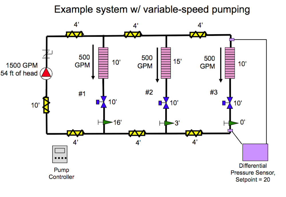
Under these conditions, there would be no flow through Zone 3, making Zone 2 our critical zone – at least for the time being. However, the differential pressure is still set for 20 feet based on the requirements of Zone 3 even though that zone is currently out of the equation. The pump does what the controller tells it to do based on the sensor reading at Zone 3 and slows way down. That’s a problem because Zone 2 needs more than 20 feet. It needs 28 (15+10+3) feet of head to deliver 500 GPM.
There are a couple of ways to fix this. One is to install differential pressure sensors on all three zones and the pump controller will make sure each zone is satisfied. It’s a bit more expensive, but a straightforward solution and one that we see quite often. Another option is to equalize the pressure drop across all three zones with the balancing valves and use 25 as your differential pressure setpoint. This also works fine – unless you have nighttime setback.
If the facility has nighttime setback, then problems could occur because of the diversity within the system and its impact on morning start-up. At morning start-up all of the 2-way valves on the system will suddenly fully open. In the case of our example, Zone 1 will overflow because it is closer to the pump. Zone 2 will get less flow than Zone 1 but more than Zone3, and Zone 3 will ultimately be shortchanged – at least until the control system has a chance to respond and the 2-way valves on Zones 1 and 2 begin to modulate. Under these circumstances, flow limiters on each zone set for the maximum zone design flow are an option. This can add complexity to the design but it will work.
If this all sounds a bit more complicated than you anticipated, don’t despair; just stay tuned for Part 12 on Pressure Independent Control Valves.
