

Variable Speed Pump Control: How Variations in Demand Load Define the Control Area
/By Chad Edmondson
In our last blog, we showed you what happens in a variable speed system when load drops. For clarity, we chose an unrealistically simple example of a system with only one coil. Today we’re going to give our system a small dose of reality by incorporating multiple zones. At the same time we hope to increase your overall understanding of “control area,” a concept introduced by Bell & Gossett in 2003.
Here is our example system with design load conditions:

Right away, you can see that we have 3 coils (or zones) instead of just one. Also note that we are using flow limiters after each control valve. (We’ll explore this further in an upcoming blog on balancing.)
What happens in this system when demand drops?
Realistically, we know valves within a multi-zone system are not opening and closing in tandem. In an actual system, we know that load varies from one zone to the next, depending on how many people occupy a given zone at a given time. It also varies from zone to zone depending on the changing solar exposure throughout the day.
Think of students in a high school migrating to the cafeteria between 11AM and 1PM. Clearly the zone serving the cafeteria is going to have a higher demand at that time of day than the classrooms, many of which will be occupied at this time. We call this “system diversity.”
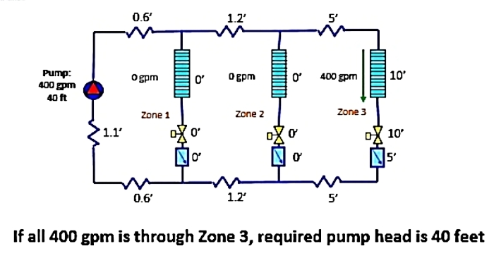
So what happens in our example system when load drops from 1200 GPM to 400 GPM? How much pump head do we need?
The answer is, it depends on where the load is. If, for example, all 400 GPM is through Zone 3, then the required pump head would be 40 feet (technically, 39.7 if you do the math!):
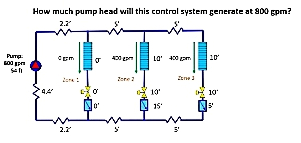
Now let’s switch it up even more. What happens if the demand is 800 GPM? Again, it depends on where the load is.
Let’s assume that Zones 2 and 3 are fully loaded. If that’s the case, we will require a pump head of 54 feet:
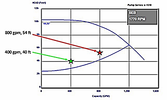
Here’s the kicker. If we had plotted a control curve for this system like we learned to do in the previous blog, we would notice that these two reduced operational points (800 GPM @ 54 ft) and (400 GPM @ 40 ft.) do not fall on our control curve. They are, in fact, above it:
These are just two points for potential “misses”. If we were to plot all of the possible operating points in this same system, it would encompass an area like this:

The space enclosed by the red curve lines represents all the possible heads and flow rates a variable speed pump must deliver in order to satisfy the part load demands of this system. On a direct return system, the upper red curve represents the pump head needed when control valves near to the pump are closing; the lower red curve represents pump head needed when control valves far from the pump are closing.
As we will see in the coming blogs, in order to prevent coil flow “misses” the area contained within the red lines is our target control area.
