

Making the Switch to Variable Speed Area Control with DP Sensor(s)
/By Chad Edmondson
What is the one piece of hardware in a hydronic system that distinguishes Variable Speed Curve Control from Variable Speed Area Control? If you said a remote differential pressure (DP) sensor you are correct. Either you’ve been paying attention, or you are a brilliant engineer in your own right.
It is the DP sensor that provides the feedback to the pump controller to speed up or slow down the pump in as needed to maintain the control head. With curve control, that head is planted squarely on the control curve. With area control, you’ve got a bit more room to play, which as we’ve learned over the last several blogs, comes in handy when you are working with systems with diversity. In both cases, flow limiters or pressure independent control valves will help owners avoid misses under certain circumstances. These automatic balance devices help by unloading pressure drop at part load conditions.

Notice that the above system is utilizing automatic flow limiting balancing valves at each zone. If we are using a curve control pump control strategy without a differential pressure sensor at the most critical zone, they will do a pretty good job of satisfying flow demand in many situations, but there are exceptions.
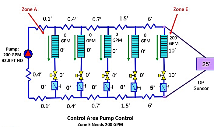
The worst-case scenario with this balance type occurs when all the load is in the most remote (critical) zone. So, what happens in our example system if we have full load in Zone E and no load in the other zones?
In that case, we will have a miss in Zone E:

Again, we have no DP sensor. Zone E is calling for 200 GPM, but we only get 162 GPM using a curve control strategy. To get the full 200 GPM through Zone E, we need a total of 42.8 feet of head. However, because of curve control, we only have 28 feet of head available to flow water through Zone E and that only gives us 162 GPM of flow. To stay within ASHRAE’s requirement of 97% heat transfer, we have to maintain at lease 90% of the design flow through that coil and 162 GPM is not 90% of 200 GPM. We need at least 180 GPM.
We can solve this problem by adding a DP sensor to Zone E, which effectively changes our variable speed control strategy from curve to area control. With a DP providing feedback to the pump controller, we can make sure that our available head across the critical zone never drops below our control head, which in this example is 25 feet. This gives us 42.8 feet of pump head at this particular part load condition – enough to give us our 200 GPM of flow through Zone E.
The remote DP sensor operates within the control area instead of the control curve. A DP sensor, plus automatic flow limiters or pressure independent control (PIC) valves at each zone, allow us to get within striking range of more load conditions in a hot or chilled system with variable speed pump control.
Area Control with Reset
In systems that have a Building Management System (BMS), keep in mind that ASHRAE 90.1-2010/13 requires that the control head be continuously reset based on the valve position so that under the least loaded conditions, there is just enough head available to keep the most critical valve nearly wide open. In other words, ASHRAE wants us to monitor the position of each valve in the system and reduce the speed of the pump until only one valve remains nearly wide open.
One word of caution – area control with reset can cause an issue if you are using pressure independent control valves. More on that in our next blog!
