How To Size A Waterside Economizer Part 5: Why Plate & Frame Heat Exchangers Are Preferred
/By Chad Edmondson
Waterside economizing typically involves the transfer of BTUs from an open loop cooling tower system to a closed loop chilled water system. Since these two hydronic systems must remain separate so we do not foul the chilled water systems, a heat exchanger is required to prevent mixing of the fluids, but what type of heat exchanger should you choose?
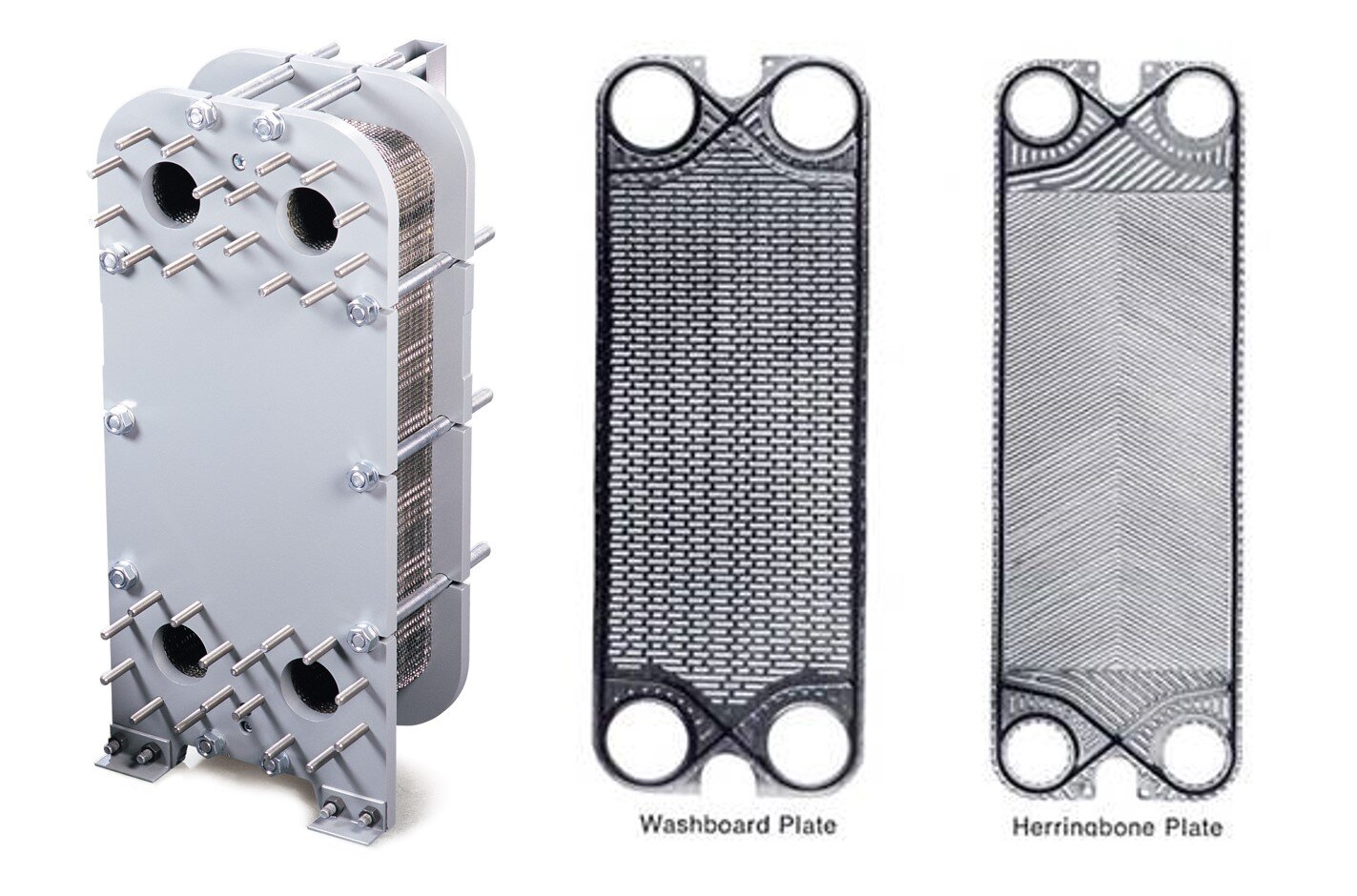
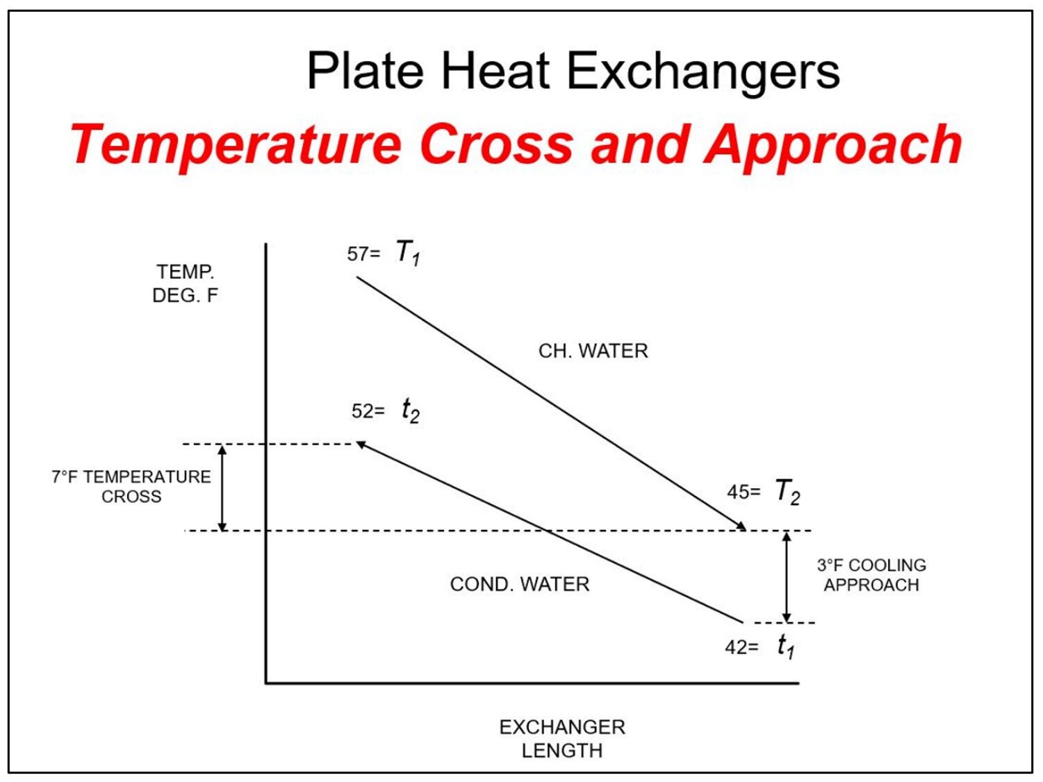
Plate and frame (P&F) heat exchangers are almost always the best choice for waterside economizers. These heat exchangers are comprised of multiple metal plates that are typically gasketed together and mounted onto a frame. There are inlet and outlet connections at the corners of the plates that allow the two fluids to enter on opposite sides. This allows the fluids to flow counter to each other thru alternating channels of the assembly. This counter flow pattern yields a high rate of heat transfer, providing as close as a two degree approach between the condenser water and the chilled water. The counter flow design also allows a temperature cross (the difference between the condenser water and the chilled water temperature at their respective outlets) which you could never get with a typical U-tube type heat exchanger.
The following diagram shows an example of a P&F heat exchanger with a three degree approach and a seven degree temperature cross.
P&F heat exchangers are compact in size and can be disassembled for cleaning. The ability to be cleaned offsets the one disadvantage that they bring to an economizing application. The narrow flow channels on the plates are more vulnerable to clogging/fouling so care needs to be taken to try to keep it clean. The cooling tower water loop should be fitted with filtration to help minimize heat exchanger maintenance. This can be done as a full stream sediment separator in front of the heat exchanger or with a sweeping system inside the cooling tower basin.
What Makes P&F Heat Exchangers So Efficient?
Most P&F heat exchangers are “single pass, counter flow.” In a single pass heat exchanger, water flows in one side of the heat exchanger and out the other side. Counter flow of course means that the two fluids (in this case, condenser water and chilled water) flow in a counter direction to each other. This flow pattern reduces the required heat exchanger surface area.
The heat transfer rate of a heat exchanger is defined by the following equation:
LMTD is a logarithmic average of the temperature difference between the hot side and cold side fluids. The larger this difference, the greater the heat transfer rate, and the smaller the heat exchanger can be.
P&F heat exchangers have high U factors (1000 units or more) thanks to the turbulence produced by the many tight directional changes in the plated channels. Again, this helps reduce the size of the heat exchanger and thus first cost.
Speaking of efficiency, ASHRAE 90.1 requires that plate type liquid-to-liquid heat exchangers used in commercial applications be certified under AHRI 400. This certification ensures that all manufacturers are designing to the same performances so that specifiers have a reliable reference for comparing equipment.
Next up we’ll talk about sizing P&F heat exchangers for an economizing application.


