

Domestic Hot Water Recirculation Part 8: Proper Application of Pressure Reducing Valves
/By Chad Edmondson
Pressure reducing valves (PRVs) are a necessary component in just about any domestic hot water system served by a high-pressure domestic water supply main. In this blog we’ll discuss how to apply PRVs properly so that these “necessary components” don’t become necessary evils that create water service problems and huge energy penalties for owners.
Never EVER Recirculate Thru A PRV!
PRVs are used to reduce high-pressure domestic water supply to more moderate pressures suitable for domestic water service. Typical domestic water systems require pressures between approximately 25 lbs. (the minimum pressure required to flush the average toilet) and 80 lbs. (the highest pressure allowed by plumbing code). For shower service, sink service, etc. it is best to keep pressures below 60 lbs., both for human comfort and the overall functionality, efficiency, and durability of the system.
This presents certain challenges in recirculation systems serving highrise buildings -- the main one being how to avoid recirculating hot water through a PRV (BAD!) while still keeping pressures within a suitable range to all floors.
Let’s say we have a 20-story hotel with a single recirculation loop like the one shown in Figure 1.
Figure 1
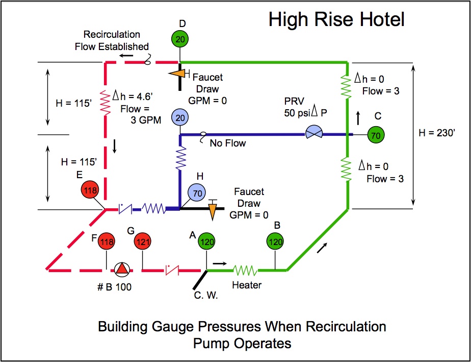
Notice the pressure gauge readings at various points in the building. Water enters at 120 lbs., goes through a single water heater and up the riser. Around the 10th floor, flow is divided between the lower and top levels of the structure. At the 10th floor and below, water pressure is at 70 lbs. – too high for shower service so a PRV is installed to absorb 50 Lbs. of pressure, reducing service water to the lower level floors to 20 lbs. Meanwhile, the top 10 floors of the building are serviced with the remaining 70 lbs. of pressure, ultimately reaching the very last fixture at 20 lbs. of pressure.
All would be well, except for the fact that this is a recirculating system, and when the recirculation flow from the top 10 floors meets up with the flow from the lower 10 floors, the latter experiences a bit of a roadblock in the pipe. We now have 70 lbs. pressure water trying to flow into 118 lbs. pressure water. Since there’s no way 70 lbs. can flow into 118 lbs., only the top 10 floors of the building are achieving recirculation. The lower 10 floors are thus starved of hot water recirculation! The hotel guests will have to dump water down the drain until the open fixtures create enough demand to get hot water from the hot water supply main.
In short, the recirculation design shown in Figure 1 will never keep all the hotel guests satisfied.
Larger Pump Not the Best Answer
A quick (but costly) fix to this problem is to add a balancing valve to the recirculation pipe coming down from the top floor, slowing the flow from these floors so that the pressure drops from 118 lbs. to 68 lbs. (Figure 2). This is just enough pressure drop in the return loop to allow return flow from the lower levels to enter into the recirculation loop and back to the pump.
Figure 2
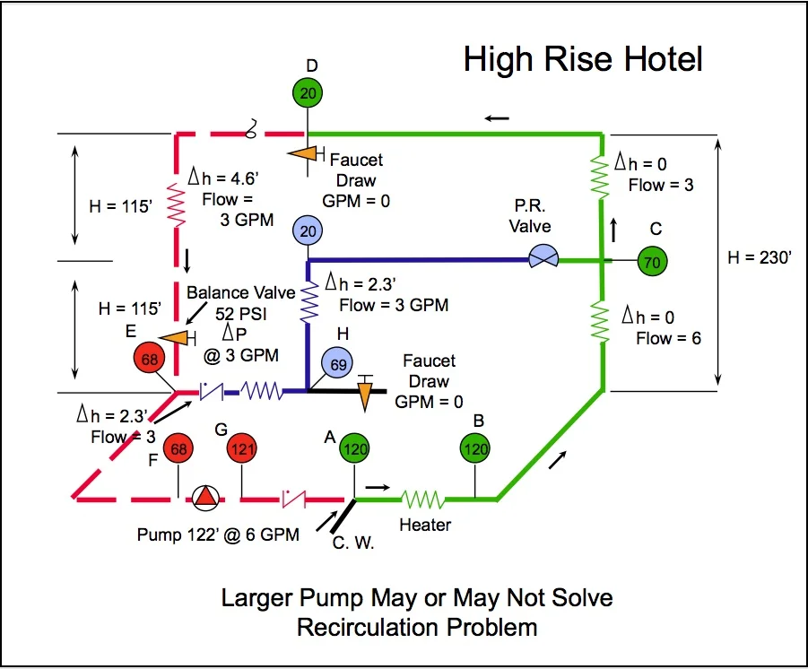
But this creates another problem. With a suction pressure of only 68 lbs. at the pump, we’ll need a higher head pump to raise the pressure above the 120 lbs. required by the water heater. In fact, we’ll need a pump (or two pumps in series) that can deliver 122 feet of head at 6 gpm. That adds up to a lot of additional energy consumption for the life of the system.
Create Separate Pressure Zones!
A better solution is to create separate pressure zones every seven to eight stories, each with its own pump and water heater. Obviously, this may not be an option if the original design was more akin to what we see in Figure 1, but it is the way most hotels (and other similar highrise buildings) are designed today. And it works.
Figure 3

Figure 3 shows how creating separate pressure zones solves the problem. Notice that the recirculation loops for the upper and lower levels of the building now operate independently of one another, and that neither has to pump through the PRV. Rather, the PRV is installed between the cold water supply and the lower level recirculation loop. It is still doing its job, reducing street water pressure into the building as needed, but it isn’t impacting the return flow pressures in any way. The upper level floors, which don’t require pressure reduction because of the static height, operate independently. The lower levels get the required reduced pressures aided by the PRV, but the circulation loop never has to cross over it.
This is, of course, a very simplified illustration. Our video on Domestic Hot Water Recirculation with Pressure Reducing Valves shows many more detailed examples of piping arrangements that are all based on the creation of separate pressure zones.
This concludes our series on Domestic Hot Water Recirculation. Be sure to check out all the previous blogs listed below, and watch our video, which covers the same material but with many more visuals!
Domestic Hot Water Recirculation Part 1: What’s The Point?
Domestic Hot Water Recirculation Part 2: Where ASHRAE 90.1 Conflicts with OSHA
Domestic Hot Water Recirculation Part 3: The Role of the Recirculation Pump
Domestic Hot Water Recirculation Part 4: Pump Sizing Example
Domestic Hot Water Recirculation Part 5: Recirculation WITHOUT a Return Line
Domestic Hot Water Recirculation Part 7: Balancing Systems with Multiple Risers
