

Domestic Hot Water Recirculation Part 4: Pump Sizing Example
/
By Chad Edmondson
Designing a domestic hot water recirculation system is not typically difficult. In fact, we see the exact same model recirculation pump used in application after application without incident, as this one pump is typically able to meet the minor head and flow requirements of most recirculation systems. That said it is important to work through the proper design procedures for any recirculation system. A little time up front can save a lot time (and money) after the fact.
First, it is important to remember the objective of your design, which is to overcome the heat loss in the pipe between the water heater and the most distant fixture during periods of no draw. Think of the recirculating portion of the system as an extension of the hot water storage. The greater the storage volume, the more BTUs that are required to keep the water hot. How many BTUs depends on the following factors:
1. The maximum temperature difference (Delta T) that you are willing to tolerate between the heater and the last fixture. This is typically 10°F, 15°F or 20°F.
2. The return portion of the recirculation piping need not be considered, as that heat loss occurs after the last fixture, and will not impact the supply water temperature.
The return portion of the recirculation piping need not be considered, as that heat loss occurs after the last fixture, and will not impact the supply water temperature.
Recirculation Design Example
Let’s work through a simple example based on the design parameters of the apartment building shown here:

With this information show here we can determine our required recirculation flow rate, size our recirculation pipe, and select the right size pump.
Determine Recirculation Rate. The recirculation rate is based on the heat loss that would occur between the heater and farthest fixture at no draw. To determine this value we consult a piping heat loss chart (Table 1). Remember, the values listed here are per 100 ft. so we apply our actual values, we will divide by 100.
Table 1

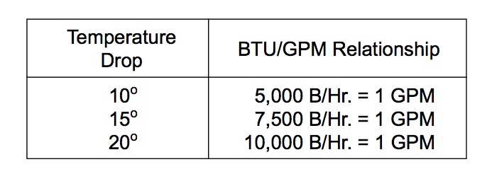
For this design, a 10°F temperature drop has been chosen. Table 2 shows us what the BTU/GPM relationship is for the various temperature drops.
Table 2
Next, based on using insulated copper tube, with 25 ft. length between risers, we can manually calculate the total supply line heat loss from the heater to the farthest riser, coming up with a total heat loss of 9320 BTUHs.

With this information we can complete our calculation to determine the necessary recirculation flow rate required to overcome the heat loss in this particular system. Since 1 gpm will convey 5000 BTUH at a 10°F ∆T, the recirculation flow rate is:
9320 BTUH/5000 = 1.87 gpm
Size the Recirculation Return Line. A sizing calculator (i.e. System Syzer) can be used to size the return line. For 1.87 gpm we would choose a ¾” copper pipe. The friction loss for this diameter supply pipe will be about 1.4 ft per 100 ft., according to the System Syzer.
Determine Pump Head & Select Pump. Given that our recirculation line is 300 feet in lenth, and our flow rate is 1.9 gpm (rounded up), we must calculate the total friction loss:
Pipe pressure drop = 300 ft. x 1.4/100 = 4.2 ft.
Check valve pressure drop = 1.0 ft.
Supply Pipe (negligible) = 0
Water Heater (negligible) = 0
Total friction head loss = 5.2 ft.
Now it is a simple mater of consulting a manufacturer’s pump curve to select our pump for 1.9 gpm at 5.2 feet of head.
Admittedly, it’s quite a few calculations to get to the definitive pump size and sizing programs are available to do most of the work. Still, it’s important to understand the logic that goes into a properly designed hot water recirculation system, especially as system designs become more complex, as we shall see in some up coming blogs.
Stay tuned, and in the meantime check out our previous blogs on this topic and our video:
Domestic Hot Water Recirculation Part 1: What’s The Point?
Domestic Hot Water Recirculation Part 2: Where ASHRAE 90.1 Conflicts with OSHA
Domestic Hot Water Recirculation Part 3: The Role of the Recirculation Pump
