

Best Practices for Hydronic Systems Part 5: Installing an Expansion Tank
/Expansion tanks are necessary to accommodate the expansion of water in hydronic heating systems. They rely on an internal air cushion that compresses as the system water heats up and expands, thus keeping the system properly pressurized at all times, regardless of temperature. Simple as they are in terms of operation, certain installation rules-of-thumb should be observed to ensure proper operation and maintain the longevity of system components.
Although not within the scope of this particular post, it bears mentioning that expansion tanks should be properly sized—otherwise you may end up with weeping relief valves or air in the system. After that, successful operation is mostly a matter of proper location of components and connection points.
Connecting the Tank
As we discussed in an earlier blog, it is important to make sure the tank piping is connected to the main piping between the air separator/water make-up and the pump suction because this establishes the point of no pressure change. The location of this connection is critical to ensuring that the air cushion inside the tank will not negatively impact system pressurization during operation of the pump.
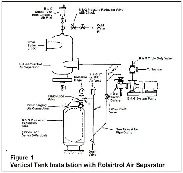
It’s not just where you locate the tank, but also how you configure the connection point between the tank branch piping and the main water line. If configured improperly, you run the risk of air pockets forming or dirt collecting in the tank. To avoid this, it is best to connect the tank branch piping so that is horizontal to the floor. In other words, if the main piping happens to be horizontal, the branch piping should connect to it at either the 3 o’clock position or the 9 o’clock position. Connecting it perpendicular to the main from above (i.e. 12 o’clock) increases the chance of an air pocket forming in the connection. Connecting it perpendicular to the main from below (i.e. 6 o’clock) increases the chances of dirt dropping into the tank connection, causing it to plug up. Figures 1 and 2 show how to properly connect the tank branch to the main, depending on the tank’s location and orientation.
If you can’t avoid connecting the pipe at the 6 o’clock position, just be sure to install a dirt leg with a drain valve to trap and flush debris.

Install an Anti-Thermosyphon Loop
We want to avoid any gravitational (thermal) circulation of water into the tank. This can be accomplished by installing what is referred to as an anti-thermosyphon loop between the tank and main connection. Figures 1 and 2 also show the correct installation of an anti-thermosyphon, given a vertical or horizontally oriented tank. The drop in the loop should be a minimum of 12-inches to prevent heat from migrating from the main and into the tank.
You also need to install the following air and pressure control devices, as shown in Figure 3:
Automatic air vent. The automatic air vent prevents the tank piping from becoming air bound. It should be installed after the anti-thermosyphon loop, at the highest point in the piping, and before connection to the tank.
Pressure gauge. This is to verify the system pressure at the tank.
Tank isolation valve. An isolation valve is necessary to service the tank without having to drain the entire system. It should be a lock-shield type to prevent tampering since it is normally open and tampering could cause discharging of relief valves in the system and a loss of a point of pressure reference for the pump.
Drain valve. A drain valve is needed to drain the piping between the tank and isolation valve prior to servicing the tank. Note: A purge valve (a combination drain and shut-off valve) can be installed instead of an individual drain and a shut-off valve.

Figure 3. Vertical expansion tank installation with proper air and pressure control devices and anit-thermosyphon loop.
Preparing for System Fill
The expansion tank needs to be pre-charged prior to connection to the system. The tank pressure should be high enough to prevent water from entering the tank upon system fill; this ensures that we have the entire acceptance volume available for water expansion once the system is up and running. Although expansion tanks typically ship from the factory with a pre-charge (typically 12 psi or 40 psi), each tank must be adjusted to the specific fill pressure for the application. A tire pressure gauge can be used to confirm the pressure inside the tank BEFORE connecting the tank to the system. If additional pressure is needed to fully charge the tank, then nitrogen gas or oil-free compressed air should be used.
