

Modern Pump Selection Part 3: Impact of Constant Fixed Head On Pump BEP
/By Chad Edmondson
In our last blog we explained why in real life HVAC applications, variable speed pumps almost never operate at zero speed. Even at no flow, the impeller must be spinning enough to produce some amount of pressure at the 2-way valve in order to quickly establish full flow at the critical circuit IF demand suddenly occurs.
Here’s a silly way to think about it. (REALLY silly, so apologies to anyone who already fully understands the concept.)
Imagine you’re watching a comedy routine in which an actor is leaning up against a closed door that opens from the opposite side. To make the bit funny, the man has to fall entirely through the door when it is suddenly opened from the other side. If he’s leaning just slightly he may stumble but not fall. However, if he is putting ALL of his weight on the door and that door flies open, he’s going to fall flat into the other room and huge laughs will surely ensue.
The actor is the water and the door is the 2-way valve at the critical circuit. The pressure the actor imposes on the door while leaning on it with his entire weight is the minimum head required at the 2-way valve to deliver full flow (big fall/huge laughs) at the critical circuit.
Now let’s think about that in terms of an actual hydronic system.
Figure 1 shows a variable speed pump curve. The purple curve represents the system curve, which also happens to be at the BEP or best efficiency point. The blue vertical line indicates the operational points for this pump at 50% flow, which in this example is 400 GPM or one half of 800 GPM. If this pump were applied to a system with no constant fixed head and all variable head, it would deliver 85% efficiency at every speed.
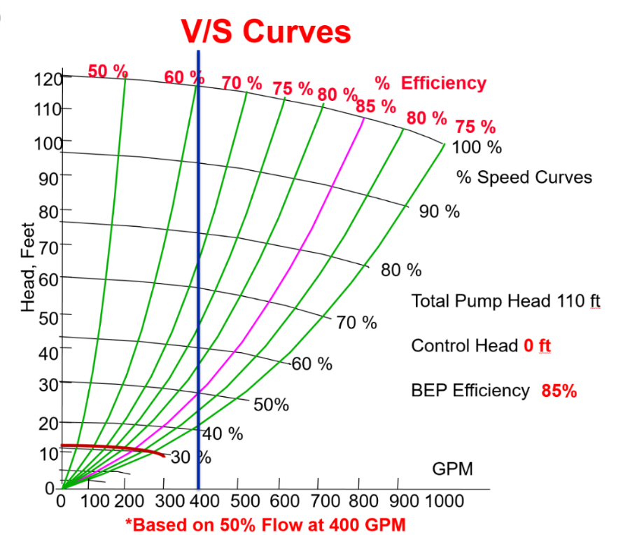
Figure 1: Purple line represents the system curve and BEP in a system with 100% variable head.
But what happens if we have a constant fixed head as most variable speed HVAC systems do? In other words, what happens to the pump efficiency when you increase the minimum control head or differential pressure set point?
For example, let’s say there is a minimum differential pressure of 40 feet. Figure 2 shows the same pump curve with a control curve of 40 feet of constant fixed head. The purple line is the new control curve.

Figure 2: Unlike the system in Figure 1, which has 100% variable flow, this system has 40 feet of constant fixed head. This significantly impacts the efficiency of this particular pump at reduced flow. At 50% flow the pump must operate at 70% speed, delivering only 72% efficiency.
Notice that at a full flow of 800 GPM we have 85% efficiency, but as we reduce flow to 50% or 400 GPM, the BEP efficiency drops. In this system with this particular pump, we have a BEP of 85% only at full flow. If we reduce flow to 400 GPM, then our BEP drops to 72%.
The intersection of the dark blue line and the purple line shows that the pump will have to operate at 70% speed in order to deliver 50% of flow. This in effect shifts the efficiency curve (shown in orange) to the left, somewhere between 70 and 75%. The orange line indicates the operating efficiency of the pump (approximately 72%) under these load conditions. If we were to continue to increase the constant fixed head, efficiency would continue to diminish.
Up next: Why You NEVER EVER Want to Overhead a Variable Speed Pump
